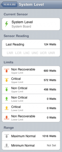
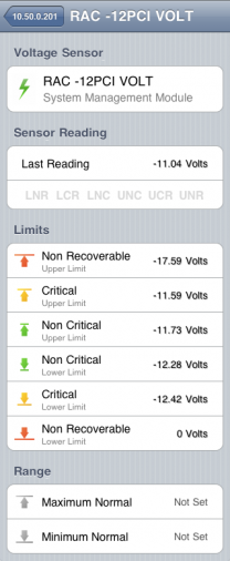
As mentioned before, version 1.2 of the application will provide means to view additional sensors and chassis information. A user will be able to tap on an individual sensor cell or on a chassis summary cell to reveal more detailed view of the item. One of the previous articles provided information on compact sensor detailed view implementation. Let’s take a look now at how detailed view will work for full IPMI sensors.
Unlike compact SDRs, full IPMI sensors usually report a value that a sensor is able to measure and a unit of measurement. To help identify fails and warnings each full sensor is also programmed with a set of limits that define normal and abnormal operational ranges; or to be more precise, upper and lower limits for non-critical, critical and non-recoverable sensor reads. It is worth mentioning that the values are intended for informational purposes only. They are not used to identify problems directly. Instead, IPMI-over-LAN protocol defines a bit-mask with six dedicated values for each abnormal event: LNR for Lower non-recoverable, LCR for Lower critical, UNC for Upper non-critical and so on.


 Comments feed
 One Response to “Detailed view for full IPMI sensors”
 Leave a Reply
Several vendors develop and market BMC chips. A BMC utilized for embedded applications may have limited memory and require optimized firmware code for implementation of the full IPMI functionality. Highly integrated BMCs can provide complex instructions and provide the complete out-of-band functionality of a service processor. The firmware implementing the IPMI interfaces is provided by various vendors. A field replaceable unit (FRU) holds the inventory, such as vendor ID and manufacturer, of potentially replaceable devices. A sensor data record (SDR) repository provides the properties of the individual sensors present on the board. For example, the board may contain sensors for temperature, fan speed, and voltage.